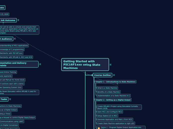
Getting Started with PIC16F1xxx using State Machines
Course Outline
Chapter 1 - Introductions to State Machines
What is a State Machine
Benefits of a State Machine
Implementation of a State Machine in C
Chapter 2 - Setting up a Digital Output
Create MPLAB X Project using Simulated Curiosity Board (SCB)
Open MCC and Configure MCU
Setup Digital I/O in MCC
Generate Application and Main.c from MCC
Create State Machine application to light LED
Demo 1 - Program Digital Output Application into SCB
Chapter 3 - Controlling a Timer
Introduction to PIC16F1xxx Timer1 and Interrupts
Setup Timer and Interrupt in MCC
Create State Machine to Blink LED
Demo 2 - Program Timer Application into SCB
Chapter 4 - Reading a Keypad to control Digital Input/Output
Introduction or Read Modify Write (Latch vs PORT)
Setup I/O for Keypad in MCC
Create State Machine for reading Keypad
Demo 3 - Controlling LED on SCB with Keypad
Chapter 5 - Serial Communications using USART
Introduction to Serial Communication with USART
Configure USART using MCC
Create State Machine for USART Serial Communication
Demo 4 - Communicate with Terminal Program from SCB
Chapter 6 - Analog to Digital Conversion (ADC)
Introduction to ADC and Potentiometer control
Configure ADC to in MCC
Create State Machine for ADC to reading Potentiometer
Demo 5 - Communicate ADC value from Pot to Serial Terminal
Chapter 7 - Using Pulse Width Modulation (PWM)
Introduction to PWM
Configure PWM in MCC
Create State Machine to Read ADC value into PWM
Demo 6 - Control LED brightness from Potentiomentor using PWM
Summary
Summary of training
Knowledge Test Quiz
Main topic
Requirements
Due Date
August 15, 2020
Major Job Outcome
Customer will be able to compile and execute their own PIC16F1xxx application using State Machines on a Microchip Demo Board using MPLAB X, MCC and XC8 Compiler.
Target Audience
Basic understanding of MCU applications
Basic knowledge of C programming
Some familiarity with PIC16F1xxx
Some familiarity with MPLAB X, MCC and XC8
Implementation and Delivery Constraints
Self-Paced Online Training
10 minute segments
Optional Lab Manual for Home study
Target 6 sections each with a demo
Windows Operating System Only
Curiosity Board Simulator within MPLAB X used for any Demos
Major Tasks
Introductions to State Machines
Setting up a Digital Output
Controlling a Timer
Reading a Keypad to control Digital Input/Output
Serial Communications using UART
Analog to Digital Conversion
Using Pulse Width Modulation