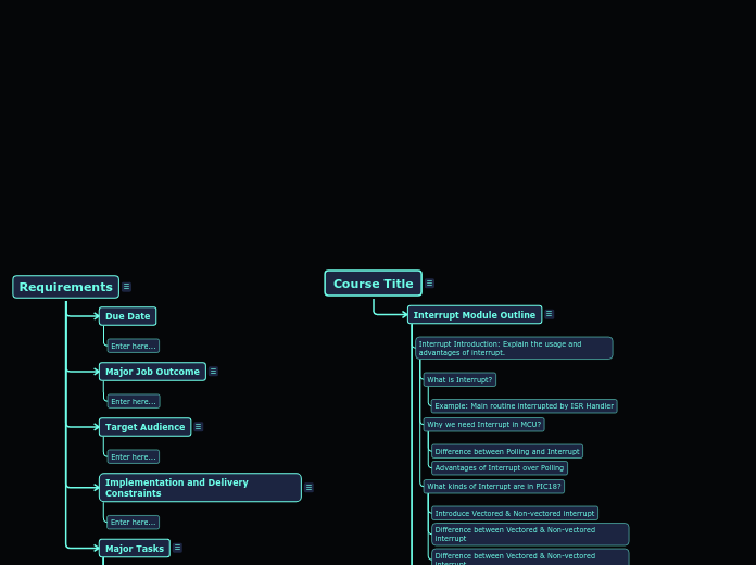
Requirements
Coaching Interview 1. Gather top-level project constraints.
Interview SME and sponsor to fill in each of the requested constraints.
Major Tasks
What are the major engineering tasks required in order to accomplish the Job Outcome?
For a Job Outcome of "Custom LoRaWAN demo application using the SAMR34 Module", we could have the following tasks:
- Evaluate the functional fitness of the SAMR34 for the demo application
- Build/purchase a hardware prototype for the application
- Download/Install firmware development tools
- Write and test firmware for the application
Major Task 9
Major Task 8
Major Task 7
Major Task 6
Major Task 5
Major Task 4
Major Task 3
Major Task 2
Major Task 1
Implementation and Delivery Constraints
Course Type (Lecture-Only, Hands-On)?
Course Duration (Hours)?
Number of instructors required?
Target Audience
Who are the major audience groups the training is targeted to?
Expected background knowledge and experience level?
Major Job Outcome
What will Attendees be able to produce or accomplish back on the job after taking this training? State it as a noun-phrase, for example:
"Customized LoRaWAN demo application using the SAMR34 Module"
Due Date
Enter here...
Course Title
Replace "Course Title" with your course title.
Add course title abstract here
Interrupt Module Outline
Coaching Interview 3. Develop a Course Outline
From the Job/Task analysis, group content together into chapters and name the chapters.
"Knowledge" (Concept/Fact/Principle) bubbles map to "Lessons"
"Procedure" bubbles map to "Lab Exercises" or "Quizzes" or other hands-on activities.
Typically, a 1:1 relationship exists between Major Tasks and Chapters. However, you are free to group knowledge and procedures from several different Tasks into the same Chapter in the course outline.
When finished, the TTE will produce a course outline in word format that captures this structure.
Atomic Operation
ISR Duration
Vector table starting address
Priority Conflict
Enable the Global and Peripheral Interrupts
6. Interrupt Pitfalls: Show some typical pitfalls using and deploying this peripheral and how you deal with them.
Demo 4: Simultaneous High- and Low-Priority Interrupts
Demo 3: High-Priority Interrupt Preempting Low-Priority Interrupts
Demo 2: High-Priority Interrupt with a Low-Priority Interrupt Pending
Demo 1: High/Low-Priority Interrupt While Executing Main Routine
Observe results in MPLAB Data Visualizer
Without Click board setup
With Click board setup
Hardware Setup
Without Click board connection
With Click board connection
Connection Diagram
5. Interrupt Demonstration: Show a working design with the configuration options you selected
o 4: Simultaneous High- and Low-Priority Interrupts
o 3: High-Priority Interrupt Preempting Low-Priority Interrupts
o 2: High-Priority Interrupt with a Low-Priority Interrupt Pending
o 1: High/Low-Priority Interrupt While Executing Main Routine
Call 4 Demos in UART terminal by typing 1/2/3/4
Describe and explain Main Routine Operation
Describe and explain TMR0, TMR1 ISR Handler
Describe the APIs and how they interface to the MCC generated code
4. Interrupt Firmware Interface: Describe the MCC generated APIs
System Module Configuration
o Enable RC2 Output Option
MCC Classic Configuration
Generate MCC Code
o Select 4 in Clock divider
o Select 4_MHz in HF Internal Clock
o Select HFINTOSC in Oscillator Select
o Set System Clock to 1MHz
Clock Control Configuration
o Set RB4 IOC option as any
Pin Module and Pin Manger Configuration
o Set TMR1 as High Priority, TMR0 & IOC1 as Low Priority
o Enable TMR0, TMR1, IOC1 interrupt
Interrupt Module Configuration
o UART1
o TMR1
o TMR0
Adding peripherals
MCC Melody Configuration
Opening MCC using MCC Classic & MCC Melody
Opening MCC using Icon & using tools bar
Step4: Type Project Name -> Click Finish
Step3: Choose XC8 (v2.32) in compiler option -> Click Next
Step2: Choose PIC18F57Q43 in Devices, PKOB nano-SN:xxxxxxxx in Tool -> Click Next
Step1: Choose Standalone Project -> Click Next
Project Creation
3. Interrupt Configuration: Show common configuration options using MCC
Case 2: IPEN = X & MVECEN = 1
Case 1: IPEN = 1 & MVECEN = 0
IVT Address Calculation
Condition and Execution with examples
Aborting Interrupts
Interrupt latency for MVECEN = 0
Timing diagram
Interrupt latency for MVECEN = 1
Interrupt Latency
PCLATH/U
PRODL/H
FSR0/1/2
BSR
WREG
STATUS
2.
1.
Chapter 3
Section 1
Lab Exercise
Lesson 1
Interrupt Hardware overview: Describe the interrupt operation and features
Context Saving Operation
CPU Registers and saving
Shadow Control Register
Context Save State Machine Diagram
Interrupt Control and Status Register
IVT1WAY, MVECEN
IVTLOCK
IVTBASE
IVTAD
IPRx
PIEx
PIRx
INTCON0, INTCON1
Interrupt Priority Operation
Priority Determination
Natural Order Priority
User Priority
Vectored Interrupt Operation
4 Common scenarios of vectored interrupt execution
Simultaneous High- and Low-Priority Interrupts
High-Priority Interrupt with a Low-Priority Interrupt Pending
High/Low-Priority Interrupt While Executing Main Routine
Vectored Interrupt State Transition Diagram
Vectored Interrupt Block diagram
Non-vectored Interrupt Block diagram
Interrupt Introduction: Explain the usage and advantages of interrupt.
What kinds of Interrupt are in PIC18?
Difference between Vectored & Non-vectored interrupt
Introduce Vectored & Non-vectored interrupt
Why we need Interrupt in MCU?
Advantages of Interrupt over Polling
Difference between Polling and Interrupt
What is Interrupt?
Example: Main routine interrupted by ISR Handler

